
Know which machine needs you before it stops the line.
A wireless sensor on every motor, pump, fan, gearbox and roll. It measures vibration, speed and temperature around the clock, and gives your team one clear status per machine: Normal, Watch, Act.
- No tachometer
- ISO 20816
- Inverter motors
- Wireless mesh
- 4–6 year battery
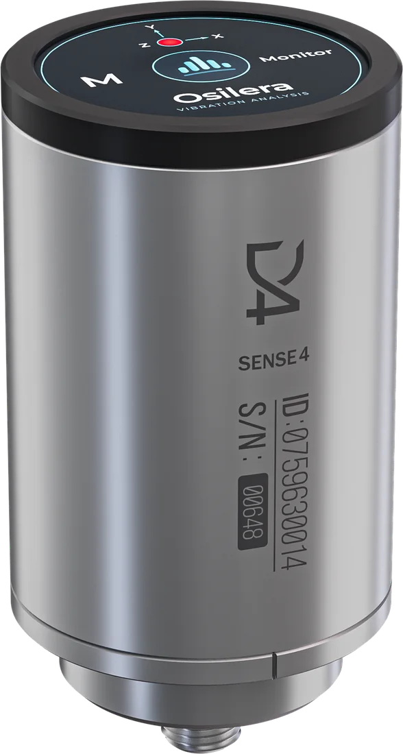
A plant runs on hundreds of machines, and most are checked once a month at best.
Motors, pumps, fans and gearboxes fail in familiar ways: a bearing wears, a rotor goes out of balance, a coupling drifts, a gear tooth chips. Each fault starts small and grows over weeks. A monthly round catches it only if someone is there on the right day.
Inverter motors make it harder. When speed changes every hour, a fixed vibration limit is too tight at full speed and blind at low speed. And many critical machines sit behind guards, on high platforms or in hot, wet areas where cabled systems cost too much.
No tachometer
Speed comes from the sensor itself. No PLC signal, no cabling.
Wireless mesh
Sensors report to a plant gateway. Mounted by stud, adhesive or magnet; no calibration.
4–6 year battery
Depending on sensor model and battery option. No wiring to install.
Managed remotely
Settings and firmware updates reach the sensor over the air.
A failing bearing gives early signs long before the machine shakes.
Most monitoring watches one number: ISO vibration velocity. It barely moves until the damage has spread. Osilera also follows the high-frequency bearing band, where a roughening race shows weeks earlier. That gives you time to order the part and plan the stop.
How a motor bearing fails, and what each measurement sees
Typical progression. A falling impact index with a rising bearing band is a late-stage sign, not a recovery.
Velocity
ISO 20816 figure on all three axes.
Speed and orders
Shaft speed, plus vibration at each multiple of it.
Bearing band
Above 2 kHz, with an impact index and envelope spectrum.
Temperature
Warning and alarm levels set per machine.
Speed changes. Your comparison still holds.
When speed changes, every vibration line moves with it, and a fixed limit either misses the fault or raises false alarms. Osilera measures the shaft speed with every reading, from 70 to 3,000 r/min, and expresses vibration as multiples of that speed, called orders. Unbalance stays at 1X and misalignment at 2X, whatever the machine is doing.
Motors
Balance, alignment, bearings and temperature.
Pumps
Vane pass and flow noise.
Fans
Blade pass, and the build-up that unbalances a fan.
Process rolls
Slow rolls compared with their neighbours on the line. Rolls and lines
A status per machine, and what to do about it.
Each machine is graded against the ISO 20816 zones for its class and against its own history at the same speed. Your team sees Normal, Watch or Act in Osilera Web. The detail is there for the analyst who needs it.
| Situation | What the sensor shows | What to do |
|---|---|---|
| Unbalance builds up | 1X rises on the radial axes | Watch: plan cleaning or balancing at the next stop. |
| Misalignment after a job | 2X and axial vibration high from the first readings | Watch: re-check alignment. |
| A bearing starts to wear | Bearing band climbs and a line appears at the defect frequency | Watch: order the bearing and plan the change. |
| Bearing damage knocks | Impact index rises: vibration turns impulsive | Act: inspect at the earliest opportunity. |
| Overall in ISO zone C or D | Velocity crosses the limit for the machine's class | Zone C: Watch. Zone D: Act. |
Osilera shows which machine is changing, in which fault family and how fast. Your maintenance experts make the repair decision, and our vibration specialists are there when you need them.
One sensor family, two bodies.
| Accelerometer | 3-axis MEMS, 26.7 kHz, ±16 g |
|---|---|
| ISO velocity | ISO 20816, 10–1000 Hz, three axes; within 1 % of a reference calibrator |
| Speed | 70–3,000 r/min, no tachometer |
| Orders | 0.5X–10X on three axes |
| Bearing analysis | Bearing band 2 kHz+, impact index, envelope spectrum |
| Peaks | Ten strongest lines per axis |
| Temperature | Surface, with warning and alarm levels |
| Network | Wireless mesh to a plant gateway; settings and firmware over the air |
| Interval | Per sensor, from minutes to hours; typically every 5 minutes |
| Battery | About 4, 5 or 6 years by model and battery option, at 25 °C and one measurement every 5 minutes |
| Mounting | Stud, adhesive or magnet; no calibration |
| Protection | IP66, −20 to +85 °C |
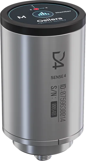
Regular use
Aluminium base and sides with a Kestamid cap.
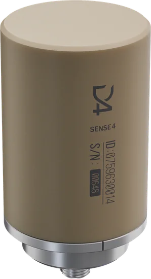
Corrosive areas
Stainless steel base with a PEEK cap, about 4 years of battery.